

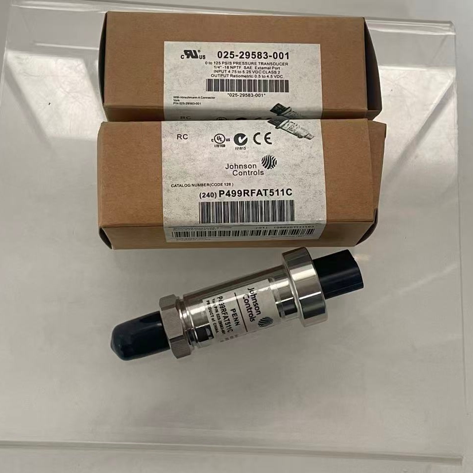
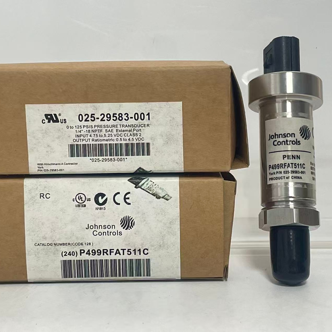
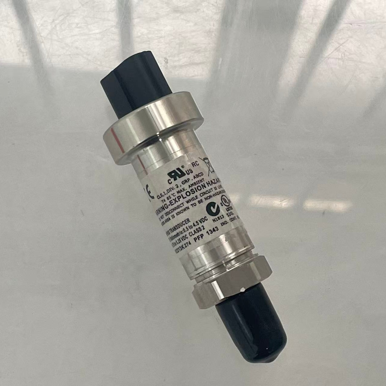
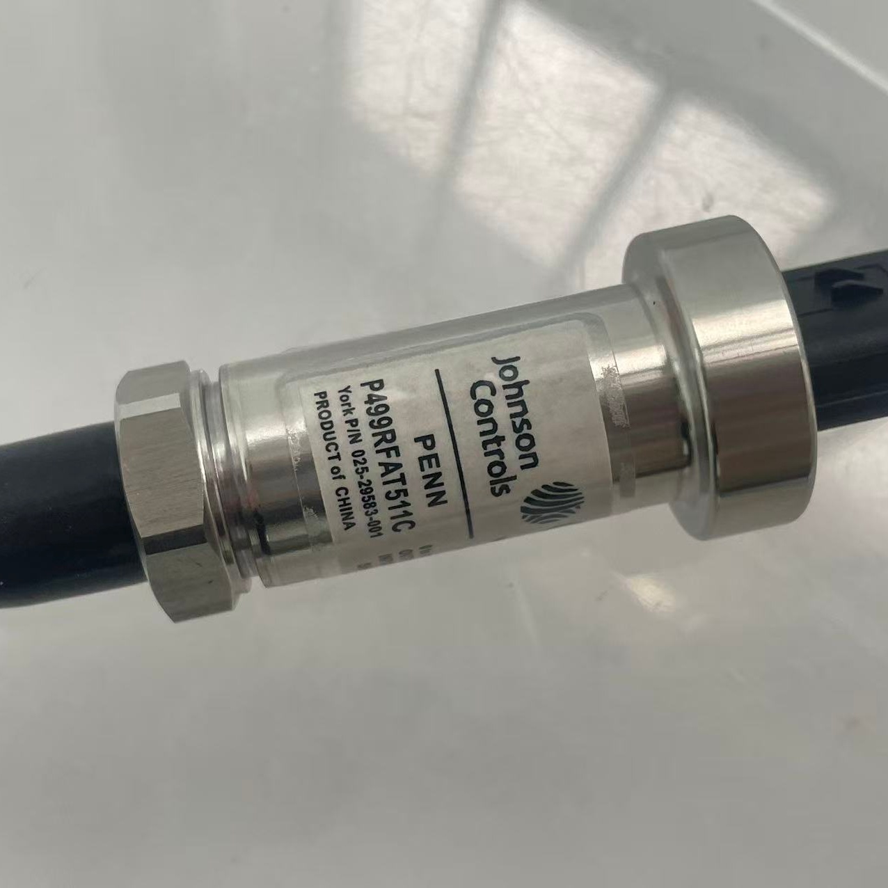
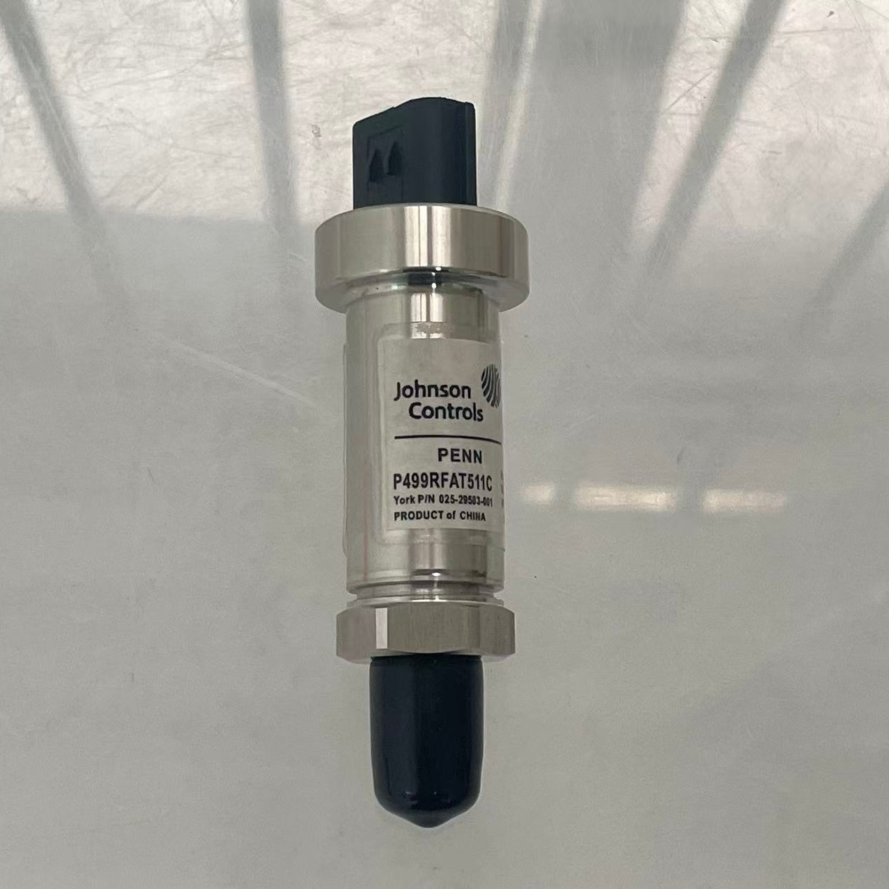
Products Description
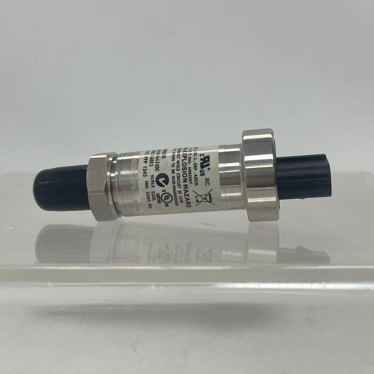
| Product Name | Yk 025-29583-001 Refrigerant Pressure Sensor |
| Model | 025-29583-001 |
| Applicable Industries | Construction and Commercial |
| Application | Refrigeration compressor |
| Packaging | Cardboard Box |
| MOQ | 1 Piece |
Common product failure symptoms:
1. Unit reports low-pressure sensor fault; compressor fails to start or load
Internal chip circuit break or wiring harness connector solder failure; no pressure signal transmitted to the main controller; compressor interlock engages, preventing operation.
2. Low-pressure reading fluctuates violently; frequent shutdowns due to anti-freeze protection
Loss of internal silicone oil or rupture of the isolation diaphragm; vibration and pressure pulses directly impact the chip, causing erratic signal acquisition.
3. Frequent evaporator icing; unit repeatedly shuts down due to anti-freeze protection
Sensor signal drift causes the main controller to read an erroneously high pressure; expansion valve opens too wide, allowing excessive refrigerant into the evaporator and causing pipe freezing.
4. Electronic expansion valve regulation failure; unit superheat fluctuates; cooling capacity degrades
Fixed deviation in pressure measurement leads to errors in the main controller’s throttling algorithm, resulting in erratic refrigerant supply regulation.
5. Persistent refrigerant leakage at the threaded connection; gradual system refrigerant loss
Degradation of thread seal tape or insufficient installation torque allows trace amounts of R134a refrigerant to leak through the threads, necessitating frequent refrigerant replenishment.
Tags: 025-29583-001 air conditioning pressure detector chiller pressure probe commercial HVAC components compressor control component cooling system sensor HVAC pressure transducer industrial chiller replacement parts refrigeration pressure sensor refrigeration system parts York pressure sensor York spare parts
Technical parameter

Company Profile
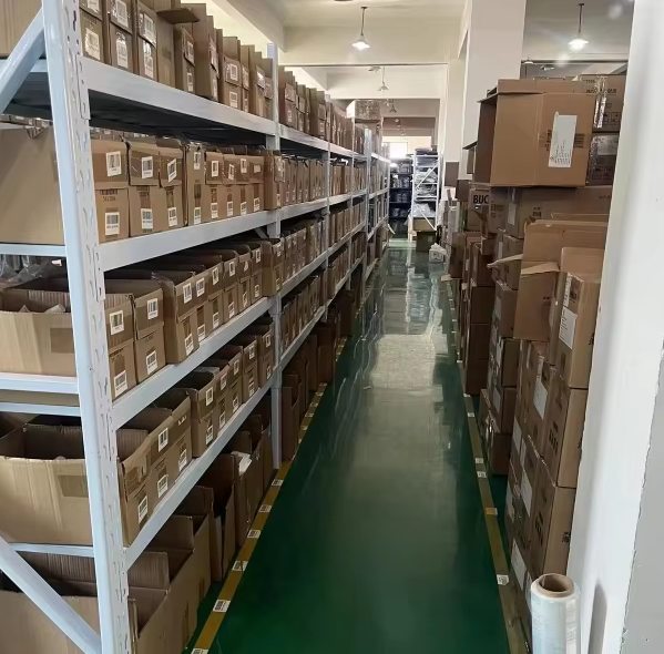
Factory Profile
| Q1:For refrigeration industry, which brands are your products covering? | A1:We produce filter element replacements for brands like,Bitzer, Carrier, Yk, McQuay, Trane, etc… |
| Q2:Does the price include freight? | A2:The quotation is usually the factory price. We can recommend the most economical logistics plan and calculate the freight according to your destination and quantity. |
| Q3:How to ensure product quality? | A3:We have a strict quality control process, and we will carry out multiple inspections before the products leave the factory to ensure that they meet the standards. |
| Q4:Why choose us? | A4:Product reliability: We are a professional manufacturer . can offer high-quality products at the most competitive prices. Technical support: We provide technical assistance. Industry experience: We have over 10 years of experience in the refrigeration equipment service field. After-sales service: We offer professional after-sales service. Team collaboration: We have a professional team that can provide you with prompt services and delivery schedules. |
Standard Product Installation Steps:
1. Installation Location: Low-pressure suction branch pipe of the evaporator; install with the threaded end facing vertically upward to ensure the silicone oil makes full contact with the diaphragm, and allow sufficient clearance for wrench operation.
Pre-installation Safety Measures
Shut down the unit completely, recover refrigerant from the low-pressure side piping, and vent pressure to atmospheric levels; disconnect the unit’s 380V main power supply and wait for the main control capacitors to fully discharge.
2. Assembly Steps
① Unplug the black waterproof wiring harness connector, use a wrench to unscrew the old 025-29583-001 sensor, and clean any sludge, rust, or debris from the base threads;
② Verify the model of the new sensor, wrap the threads with a small amount of refrigerant-resistant PTFE tape, screw it in by hand, and then tighten slightly with a wrench (do not use excessive force, which could strip threads or damage the base);
③ Reconnect the 3-pin waterproof wiring harness, ensuring the connector latch is fully locked and the connection is secure;
④ Perform a nitrogen pressure test at 125 PSI and hold for 30 minutes; the installation is considered successful if there are no refrigerant bubbles or leaks at the threaded connection;
⑤ Evacuate the piping and charge with refrigerant; run the unit at no-load for 10 minutes and verify that the low-pressure reading on the touchscreen is stable without fluctuations; run at full load for 30 minutes and verify that the expansion valve regulates stably without triggering low-pressure fault alarms.
3. Criteria for Replacement
Touchscreen displays no low-pressure value or a fixed, unchanging value; main controller reports an open-circuit or out-of-range sensor fault;
Pressure readings fluctuate violently; unit frequently shuts down due to random low-pressure protection trips;
Continuous refrigerant leakage (bubbling) at the sensor threads; internal isolation diaphragm is corroded or damaged;
Severe signal drift due to long-term use; anti-freeze or superheat control logic is erratic and cannot be calibrated. 4. Usage Precautions
Do not use interchangeably with the 025-29139-001 high-pressure (400 PSI) sensor; the measurement ranges and output curves do not match, which can easily cause chip breakdown. Do not install the sensor upside down or horizontally, as silicone oil leakage or trapped air pockets will lead to significant reading errors. Strictly prohibit connecting or disconnecting the wiring harness while the power is on, as voltage surges can damage the internal sensor chip.