

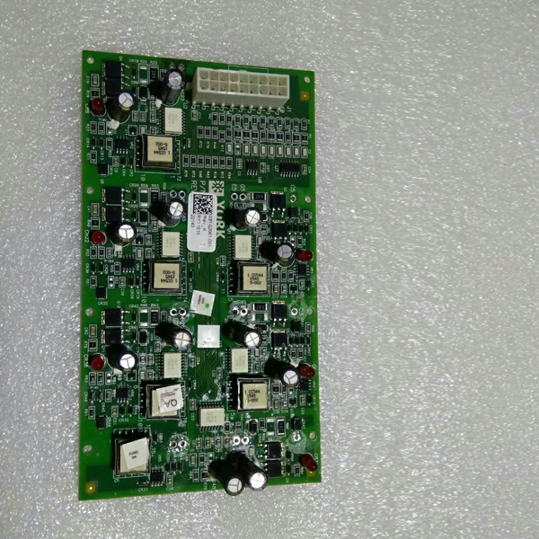
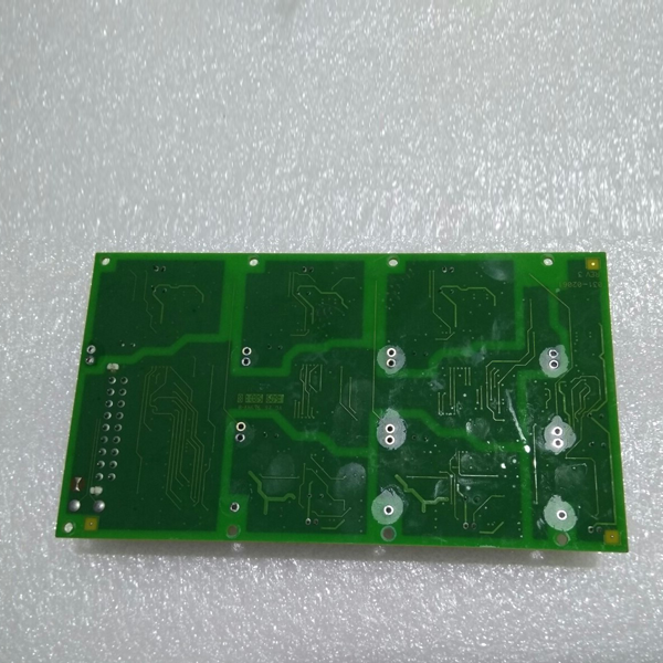
Products Description
| Product Name | Yk 031-02061-001 Circuit Board |
| Model | 031-02061-001 |
| Applicable Industries | Construction and Commercial |
| Application | Refrigeration compressor |
| Packaging | Cardboard Box |
| MOQ | 1 Piece |
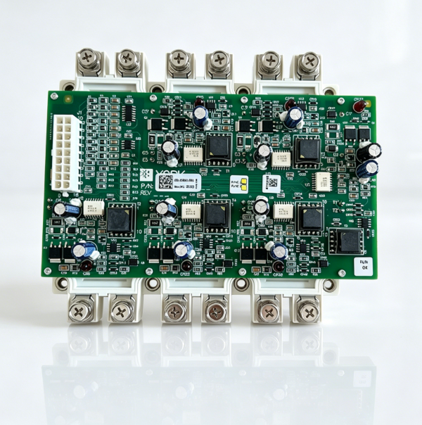
York 031-02061-001 Variable Frequency Drive Board: Core Functions
1. Variable Frequency Drive (Core Function)
Converts three-phase utility power into variable-frequency, variable-voltage AC power to drive the variable-speed compressor, enabling stepless speed control from 0% to 100%. Lower rotational speeds result in lower power consumption; under partial load conditions, energy savings of 30%–50% can be achieved, significantly improving the Integrated Part Load Value (IPLV).
2. Precise Cooling Capacity Regulation
Receives 4–20mA or communication signals from the YMC2 main controller and adjusts the compressor speed in real-time based on outlet water temperature or load demand. Cooling capacity output is continuously adjustable from 10% to 100%, achieving temperature control accuracy of ±0.5°C and preventing frequent start-stop cycles.
3. Soft Start / Soft Stop
During startup, the frequency and voltage ramp up gradually; the starting current remains ≤ 1.2 times the rated current, ensuring no inrush current or mechanical shock, thereby extending the compressor’s service life. During shutdown, the frequency ramps down gradually to prevent liquid slugging and system pressure fluctuations.
4. Real-time Status Monitoring and Feedback
Features onboard sampling circuits for current, voltage, temperature, and rotational speed, allowing for real-time monitoring of operating parameters and feedback to the main controller. In the event of a fault, an immediate alert is issued, displaying specific fault codes (e.g., overcurrent, overheating) to facilitate rapid troubleshooting.
5. Multiple Protection Mechanisms (Safety Core)
Overcurrent Protection: If the output current exceeds limits, the unit immediately reduces frequency or shuts down to protect the IGBT module and compressor windings.
Overvoltage / Undervoltage Protection: Disconnects the output when the DC bus voltage becomes abnormal to prevent module breakdown.
Overheating Protection: Issues a warning when the IGBT temperature reaches ≥ 85°C and initiates an emergency shutdown at ≥ 95°C to prevent burnout.
Short Circuit / Ground Fault Protection: Shuts down the unit within microseconds in the event of an output short circuit or ground fault to prevent major accidents.
Loss-of-Synchronization Protection: Rapidly adjusts the frequency if the compressor loses synchronization to prevent rotor stalling. 6. Operation in Conjunction with the Trigger Board
Used in conjunction with the 031-02060-001 (SCR Trigger Board): The trigger board handles signal isolation, pulse amplification, and IGBT triggering; the drive board handles power output, current sampling, and protection execution. Together, these two components work in tandem to achieve precise variable-frequency control.
Tags: air conditioning circuit board chiller control board chiller electrical board chiller main board chiller replacement board circuit board commercial chiller component control board cooling system control board electronic control board hvac circuit board HVAC Spare Parts industrial HVAC control module refrigeration circuit board refrigeration control board refrigeration equipment board York 031-02061-001 York chiller parts York circuit board York HVAC spare parts
Technical parameter
| Q1:For refrigeration industry, which brands are your products covering? | A1:We produce filter element replacements for brands like,Bitzer, Carrier, York, McQuay, Trane, etc… |
| Q2:Does the price include freight? | A2:The quotation is usually the factory price. We can recommend the most economical logistics plan and calculate the freight according to your destination and quantity. |
| Q3:How to ensure product quality? | A3:We have a strict quality control process, and we will carry out multiple inspections before the products leave the factory to ensure that they meet the standards. |
| Q4:Why choose us? | A4:Product reliability: We are a professional manufacturer . can offer high-quality products at the most competitive prices. Technical support: We provide technical assistance. Industry experience: We have over 10 years of experience in the refrigeration equipment service field. After-sales service: We offer professional after-sales service. Team collaboration: We have a professional team that can provide you with prompt services and delivery schedules. |
Key Points for Product Installation and Maintenance
1. Power Disconnection + Discharge Procedure: Before installation, cut off the unit’s main power supply and wait 10 minutes (to allow the busbar high voltage to discharge) to prevent electric shock.
2. Installation Location: Install the unit inside the VSD control cabinet; mount it vertically with the heat dissipation vents facing upward, ensuring a clearance of ≥10 cm around the unit for heat dissipation. Keep the unit away from high-temperature exhaust pipes and transformers.
3. Wiring Standards: Connect the three-phase inputs (L1/L2/L3), outputs (U/V/W), communication lines (RS485), and power supply lines to their corresponding terminals; ensure all terminals are securely tightened and that the shielding layers are properly grounded.
4. Heat Dissipation Inspection: Before installation, clean any dust or oil residue from the heat sink fins. After powering on, verify that the cooling fan is rotating normally and is free of abnormal noises.
5. Power-on Commissioning: After powering up, use the YMC2 main controller to trigger a variable-frequency startup; monitor the rotational speed, current, and voltage to ensure they are within normal parameters. Check for any fault codes and clear the fault history.
6. Periodic Maintenance: Conduct quarterly inspections to check for dust accumulation on the heat sink fins, proper fan operation, loose wiring, bulging capacitors, and the status of indicator lights. Perform an annual calibration of the current and voltage sampling circuits; replace components immediately if any anomalies are detected.